現代TEM/STEM系統有二大影像模式:TEM影像和STEM影像。TEM影像如圖B-24所示,包含明場(BF)像,暗場(DF)像,和高分辨(HRTEM)影像三種。前二種的分辨率在0.3 ~ 0.4 nm之間,倍率範圍從1000X 到100KX之間;HRTEM影像的分辨率可達到約0.16 nm,倍率範圍從100KX 到1000KX之間。STEM影像有明場像,環形暗場(ADF)像,高角度環形暗場(HAADF)像,高分辨(HRSTEM)影像(通常倍率大於5MX)等幾種。STEM影像的好處是影像可以自由旋轉,對於半導體元件的影像,很容易將基板和薄膜的界面調成水平方向。2015年後的TEM如果安裝4K x 4K的CCD或CMOS數位相機,只擷取2K x 2K的影像,也有同樣的功能。
There two main types of images, TEM images and STEM images, for current TEM/STEM systems. TEM images include bright-field (BF) images, dark-field (DF) images, and high resolution TEM (HRTEM) images, as shown in Fig. B-24. The routine magnification for both BF/DF images falls in the range of 1000X to 100KX, the best resolution of BF/DF images is about 0.3 to 0.4 nm. The magnification used for HRTEM images is from 100KX to 1000KX, and the resolution approaches 0.16 nm. STEM images include bright-field images, annual dark field (ADF) images, and high angle annual dark field (HAADF) images, high resolution STEM (HRSTEM) images (> 5 MX). The advantage of STEM images is free to rotate images, so all STEM images of semiconductor devices can easily be set all interface running horizontally. For TEMs manufactured after 2015 and equipped with a 4K x 4K CCD (or CMOS) camera, all TEM images can do the same rotation if only images of 2K x 2K taken.
圖B-24. TEM模式下的典型影像。(a)明場像;(b)中央暗場像;(c)高分辨影像;(d)和局部放大高分辨影像。
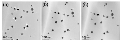
嚴格定義的TEM明場像是使用最小的物鏡光圈,只讓透射電子束通過成像,但是此種影像對比過於強烈,影像非黑即白缺少灰階變化,所以除非分析晶體缺陷,很少使用此類型的明場像,而是用大一點的物鏡光圈,包含部分第一階的繞射電子束,緩和影像對比,在影像中增加一些灰階層次。在這類型的TEM明場像,物鏡光圈除了調整對比外,也有減少物鏡球面像差的功能,如圖B-25所示,在無物鏡光圈時,某些黑色顆粒的旁邊會有一形狀大小相同的“亮”顆粒,放入100 um的物鏡光圈後,大部分“亮”顆粒消失,只剩下一,二顆微粒的側緣有亮線,這是物鏡球面像差造成的影像,所以在使用30 um物鏡光圈的影像內這些假像完全消失。根據經驗,分析奈米材料時,必須使用60微米以下的物鏡光圈,才能得到清晰且沒有亮點假象的奈米相TEM明場像。
The strict BF image means those images using the smallest objective aperture to block all diffracted beams and allowing only the transmitted beam to pass to form the image. The contrast of this kind of BF images is too high, absent of grey levels. We use this kind of BF image to analyze crystal defects only. We usually use a larger objective aperture to include several diffracted beams as well as the transmitted beam to form BF images with tones of grey. Besides changing the contrast of images, the objective aperture can reduce spherical aberration, as illustrated in Fig. B-25. Some particles in the BF image without objective aperture are coupled with a “bright shadow”, all of these “bright shadow” disappear when a 100um objective aperture is used, butl a few of particles with bright lines aside are still observed. There is no bright line observed at any particle when a 30um objective aperture is used. According to experience, it is better to use objective aperture not larger than 60um to minimize the effect of spherical aberration to obtain clear BF images of nano phases, especially nano wires.
圖B-25. TEM明場像。(a)無物鏡光圈;(b)物鏡光圈 = 100 um;(c)物鏡光圈 = 30 um。
一般的TEM暗場像一定使用小於30 um的物鏡光圈擋住透射電子束和其他的繞射電子束,只讓某一特定的繞射電子束通過成像。而且此繞射電子束必須傾轉到光軸上,形成中央暗場(CDF)像,暗場像上的的球面像差效應最小,影像才會清楚,如圖B-26所示,只有在中央暗場像才看得到鎢矽化物內的疊差,而偏離光軸的暗場像因球面像差之故,分辨率不足,無法解析細微的結構。
Generally, a TEM DF image uses an objective aperture < 30um to block transmitted beam and other diffracted beams, only allow one specific diffraction beam to pass through to form a DF image. This selected diffracted beam should be tilted to go along the optical axis to for a center dark field (CDF) image that minimize the effect of spherical aberration in the DF image, as shown in Fig. B-26. The tiny structure, such as a stacking fault in the tungsten silicide, can only be observed in the CDF image, but not in the DF image that has significant spherical aberration resulted from using an off-axis diffracted beam.
圖B-26. TEM模式下的明場像(a),對應的暗場像(b),與中央暗場像(c)。
可以得到前述二種影像的試片和機台條件,不一定可以得到HRTEM影像。要得到足夠清晰的HRTEM影像,下列幾個條件必須同時滿足。(1)試片必須是晶體而且夠薄,而且因試片製備造成的表面損傷層要更薄;(2)晶體的低指數晶軸(low index zone axis)要能夠被傾轉至和電子束平行;(3)TEM物鏡散光必須調整至接近零的狀態;(4)適當的物鏡欠焦(under focus)。
It is easy to acquire both BF and DF images when a TEM specimen is inserted, but it requires some special conditions to get good HRTEM images. First, the TEM specimen must be a crystal and thin enough with a very thin damaged layers on the surfaces. Second, the low index zone axis of the crystal has to be tilted parallel to the TEM optical axis. Third, TEM must be well aligned especially the astigmatism of the objective lens. Fourth, optimum under focus has to be used.
STEM明場像可用STEM BF影像偵測器攝取,也可用環狀影像偵測器搭配大於3米的相機長度攝取。整體來說,STEM明場像和TEM明場像很類似,但是因試片彎曲造成的條紋,在STEM明場像中可以被緩和許多。當相機長度逐漸減小時,環狀影像偵測器內收集角逐漸變大,透射電子束直接穿過中間中空區域,只有繞射電子束形成影像,是為環形暗場像。當相機長度變得很小時,環狀影像偵測器內收集角變得很大,環狀影像偵測器只收集到被彈性散射到高角度的彈性散射電子,此時攝取到的影像是為高角度環形暗場像。相機長度,內收集角,和收集訊號種類的關係說明於圖B-27中。
STEM BF images can be acquired by an annual dark filed (ADF) detector as well as a STEM BF detector. When a ADF detector is used to acquire STEM BF images, a large camera length (CL) has to be used. STEM BF images look similarly to corresponding TEM BF images. However, many bend contour fringes in TEM BF images can be eliminated in STEM BF images. The inner collection angle of the ADF detector increases gradually when the CL becomes small and small. The ADF detector then collected signals in diffracted beams only, so we call this kind of images to be annual dark field images. The inner collection angle of the ADF becomes very large when the CL becomes very small. Only those electrons elastically scattered to high angles are collected at this moment, STEM images at these conditions are called high angle annual dark field (HAADF) images. Relationships among CLs, inner collection angles, and signals are described in Fig. B-27.
圖B-27. STEM模式下相機長度(CL),內收集角(θin),和收集訊號種類的關係。


沒有留言:
張貼留言